Power amplifiers, TPA boards.
You may download the schema in PDF and/or the zipped Eagle files of the TPA-2 board.
The power amplifiers are based on the TPA3255 chip from Texas Instruments. Datasheet Also have a look at the TI evaluation board for this chip.
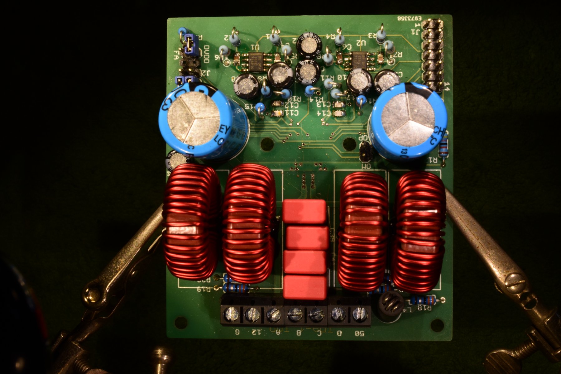
Note: The board in this picture is TPA-1. TPA-2 has some minor modifications but is not yet manufactured.
The TPA3255 has 4 class D amplifiers which can be configured in different ways.
My system uses 2 identical boards (TPA2), one for Bass and one for Midrange and Tweeter.
With jumper settings and component options the Bass board is configured as Parallel BTL, being able to deliver up to 300 Watt in a 4 Ohm loudspeaker, the Midrange and Tweeter board is configured as 2 x BTL, giving up to 150 Watt in 8 Ohm for each channel.
To prevent ground loop problems as much as possible I used differential drivers on the FLT board and differential receivers on this board OPA1632.pdf.
The TPA3255 channels have to be driven differentially anyhow.
The supply voltages for the differential receivers are taken from the FLT-board. The two TPA's are configured such that one is a master PWM clock and the other is slave. In that way no low-frequency interference is possible because of slightly different PWM frequencies. In such a master-slave configuration the chips do their PWM even out of phase to reduce radio frequent emission.
Do pay attention to the HF inductors. This type (MA5172-AE.pdf), also used in the TI evaluation module, does not show a reduction of inductance with currents up to 40 Amps. Many same looking inductors show this behaviour already with a few Amps. These inductors are in the loudspeaker ciruit, outside the feedback loop, so any non-linearity will produce distortion. A calculation: 10 uH at 10 kHz has a reactive impedance of 0.63 Ohm. If this inductance is modulated by other frequencies you will certainly hear distorsion.
The TPA chips are supplied with +50 Volt PVDD for the power part, and +12 Volt for the control part.
The board layout is quite critical. The abundancy of decoupling capacitors should all be as close to the chip as possible, and the traces for PVDD and loudspeaker should be as wide as possible. An as good as uninterrupted ground plane is an absolute must.
Because of the high currents it is advisible to make this board with thicker copper than the usual 35u. I used 60u.
The TPA3255 chip is very thin. I use a small 2mm thick aluminium plate between the chip and the cooling body because without it the smd-components on the bottom side of the board would short-circuit with the cooling body.
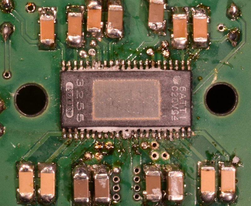
The TPA3255 on the bottom of the TPA board.
This chip is even shorter than a DIL14, but has 22 legs on each side. To hand-solder it to the PCB you really need a stereo microscope and a solder iron with a very small tip. The gray matter here and there is a residue of thermal coupling compound.
Mount options for Bass in PBTL and Mid, Tweeter in BTL. MS = Master-Slave clock operation.
| Component: |
Bass: |
Midrange, Tweeter: |
| R3, R4, C5, R7, U2, R8, C8, C9, C10, R11, R12 |
Do not mount. |
Do mount. |
| C13, C14 |
Do not mount, Bridge to GND. |
Do mount. |
| Header J2 |
jumper pin 3-5. jumper pin 2-4. |
jumper pin 3-5 jumper pin 4-6 |
| Header FA-DVDD |
Leave open. |
For MS: jumper FA-DVDD to stop local
oscillator. |
| Header MP |
For MS: Connect to other board. |
For MS: Connect to other board. |
| Loudspeaker connections |
A-C--+-Loudspeaker----B-D |
A--+-Tweeter----B
C--+-Midrange----D |
THD + N, or how to clutter the specifications.
A note about the distorsion specifications in the datasheet of the TPA3255 (and most other audio devices)
Total Harmonic Distorsion (THD) is mostly specified in combination with noise, THD + Noise, and in % of the output signal level.
Noise is the random fluctuation of currents and voltages in resistors and semiconductors. When audible it sounds like the hissing of a high-pressure cooker or some other steam engine.
THD is the total effect of all non-linearities in the device which produce harmonics and intermodulation (= sum and difference frequencies).
These two phenomena arise from totally different mechanisms and have nothing in common. Why then are they specified together?
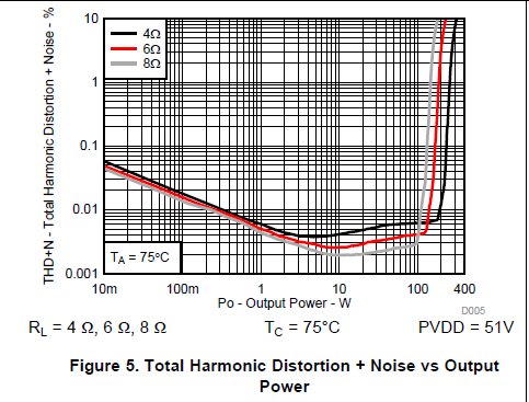
Well that is the lazyness of the technicians who must fill in the datasheets. At low signal levels it is quite difficult to distinguish between Noise and THD, Noise wins, distorsion drowns into what we call the noise floor. See figure 5 from the datasheet. Below 2 watts we see the THD + N rise. Is that THD or Noise? Well it is very uncommon that THD increases with lower signal levels. And noise is independent of the signal level. But this graph has a percentage of signal strength on the vertcal axis, so the constant noise appears to increase, but that is nonsense, the signal level decreases!
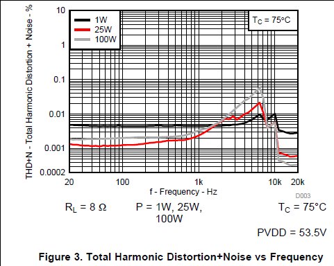
In figure 3 we see THD + N much higher at 1 Watt than at 25 or 100 Watt. Does distorsion decrease at higher output power? Unlikely. What we see here is that below 5 kHz the noise dominates over the THD at 1 Watt. For higher output power this dominance starts at lower frequencies, not because the device performs better, but because the vertical axis of the graph is in % of the output level.
This all makes these graphs difficult to read properly. An excuse might be that THD is supposed to be inaudible when it is below the noise level. Maybe, but I do not think it a good excuse to mix these things.
Is there a way to better separate THD from Noise? YES! But it takes somewhat more time. If one uses a very pure sinewave generator and a spectrum analyser with averaging capabilities one can separate harmonics and intermodulation from the random noise by averaging the spectrum over a longer time. But time seems to be costly and so manufacturers of even high quality audio products leave us in the mist of cluttered graphs.