Electro Static Loudspeaker
In brief:
For those who are not familiar with ESL's a few words about the principle.
A spreadsheet is presented for the most important calulations.
Some measurements were done to find properties of the transformer and the modules.
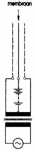 Electrostatic
loudspeakers generally consist of two acoustically open and
electrically conductive plates (e.g. perforated metal) called
the Stators, and in between an electrically conductive foil
called the Membrane. The stators are symmetrically driven by a
so called Step-Up transformer which converts the output voltage
from the amplifier to hundreds or a few thousand Volts.
Electrostatic
loudspeakers generally consist of two acoustically open and
electrically conductive plates (e.g. perforated metal) called
the Stators, and in between an electrically conductive foil
called the Membrane. The stators are symmetrically driven by a
so called Step-Up transformer which converts the output voltage
from the amplifier to hundreds or a few thousand Volts.The membrane is held at a high DC voltage, 2 .. 5 kV is not unusual, symbolized by the battery in the drawing left.
The transformed signal voltages drive the membrane by electrostatic forces.
A requirement is that the electrical charge on the membrane stays constant. If it changes with the displacement of the membrane there will be intermodulation distorsion. To realise this constant charge one can do one or both of two things, connect the membrane to the high voltage source trhrough a high resistor, many MegOhms, and/or use a membrane with a very high area resistance. The high voltage source is permanently switched on in most cases. For many ESL's it takes minutes to build-up the charge.
The distance between the membrane and the stator is around 1 mm, the area of stator and membrane can be from a few to many tens of dm2. The smaller units are used for the highest and midrange audio frequencies, for a full-range ESL a large area is required.
Because the membrane is chosen very thin (usually 2..4 microns) it has very little mass and so can easily move at high frequencies. This is the primary reason why ESL's provide such clear and resonance-free mid- and high frequencies, compared with e.g. squakers and dome tweeters where substantially more mass has to move.
Of course there are disadvantages too:
Because the area of the membrane is much larger than e.g. the membrane of a dome tweeter, the radiation is very much in one direction. Yes, there are ways to overcome this, but anyhow....... In my design with the cone this problem with directivity is absent.
ESL's are basically dipole radiators, equal amounts of sound emit from the front side as from the back side. For the lower frequencies this requires a large baffle, because otherwise the radiation from front and back will cancel each other. Reproduction of very low frequencies is nearly impossible.
On the other hand, homebuilding ESL's is very well feasable, the materials are not very expensive and there is a large community of DIY ESL builders. Before you start your own project, read the literature and the experiences of others.
Picture from Fikier: "Elektrostatische Luidsprekers" (NL), published by (at that time) Elektuur, 1993.
For my system I used 4 modules (2 for each unit) from a set of old-model Solosound loudspeakers. https://www.solostatic.com/
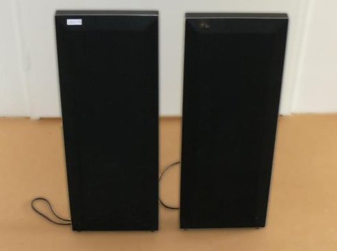
Solosound v 4 (picture taken from www.marktplaats.nl)
The original Solosound system consists of these units and separate bass boxes. The ESL's operate from around 300 Hz up.
Somewhere in the eighties I bought a used set of these ESL's without the bass units and combined them with transmissionline bass/mid-units with KEF B139 and KEF B110. (SOTA, State Of The Art)
These ESL's each have 4 modules like below, mounted on a hard-foam body of 28 x 76 cm.
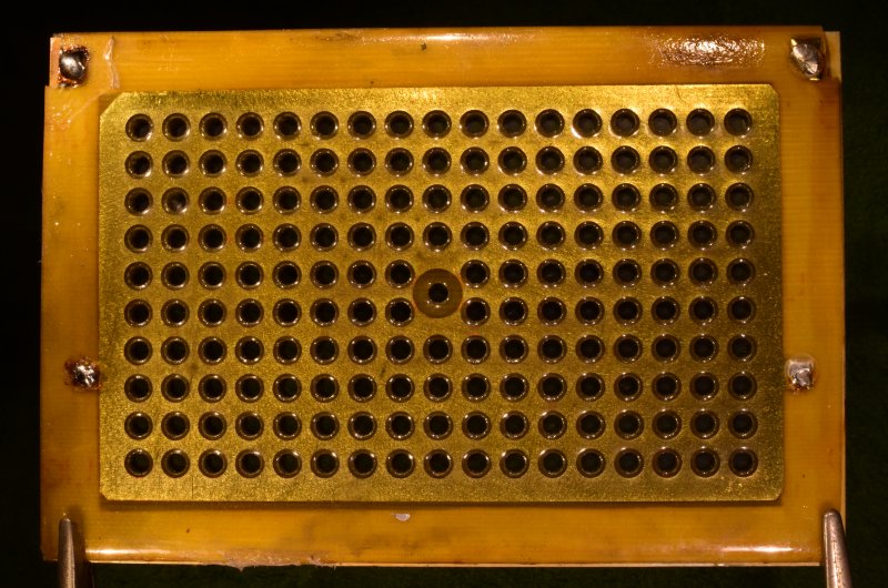
Solosound Module. Outer size 100 x 150 mm.
Each module is a sandwich of stator-PCB, spacer, membrane, spacer, other stator-PCB.
The stator PCB's have the metal layer on the outside, covered with a layer of some laquer for insulation. Remember we may have over 8000 Volts between the metal and the membrane. Normally 1000 .. 2000 Volts will produce sparks in 1 mm of air.
The membrane is made of a very thin plastic foil, which has been made electrically conductive with a material having a high surface resistance.
The membrane is connected to the high-voltage source, the Stator-PCB's are symmetrically driven by the step-up transformer. The solder joints at the top of the picture connect to the membrane.
Fill factor, or how "open" are these stators:
The holes are 4 mm, so they have a surface area of 12.6 mm2. We have 170 holes, so 2140 mm2.
The metallized area is 119 x 72 mm, or 8570 mm2. Fill factor = 2140 / 8570 = 0.25. This makes me consider a better design in future.
High Voltage Unit.
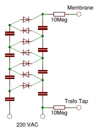 To the left the
schematic, drawn here with 7 diodes to demonstrate the principle
of a cascade voltage multiplier.
To the left the
schematic, drawn here with 7 diodes to demonstrate the principle
of a cascade voltage multiplier.The actual Solosound unit has 16 diodes and 16 capacitors and so will produce around 5000 Volts.
The capacitors (47 nF) and the diodes must be capable of withstanding at least 1000 Volts each.
The circuit is directly connected to the mains voltage, which makes it cheap but not so safe, although it is connected to the ESL by high value resistors.
The power consumption however is almost nothing, after the charge has been built up.
Measurements on the ESL module.
With a caliper I measured the distance between membrane and stators to be 1 mm, the board thickness was 0.8 mm.
The electrical capacitance was found to be 35 pF for 1 module and 81 pF for both, including wiring capacitance. Measured with a LCR-meter.
Measurements on the Step-up transformer.
The DC resistance of the primary is 70 milliOhm, the secondaries have 54 and 60 Ohm for each halve.
The step-up ratio was found to be 1:87:87 or 1:175 from primary to stator-to-stator.
With the now known capacity of the ESL's we can calculate the capacity to be seen on the primary side of the transformer. 81 * 175 * 175 = 2.48 uF.
Measuring with the LCR-meter on the primary side gave 4.5 uF. The difference must be the parasitic capacitance inside the transformer.
To find the inductance of the secondary I connected a capacitor of 47 nF, much larger than the parasitic capacity, injected a signal through a resistor of 30 kOhm and tried to find a resonance by sweeping the frequency. From C and Fres I could calculate the inductance. It turned out that the inductance was very much dependant on the signal level applied. At small signal levels the inductance decreases dramatically.
I found 14 H at 1 Volt RMS, 38 H at 10 V RMS and 80 H at levels of 90 V and up.
The reason for this decrease with lower signal levels is the very non constant μ, the relative pemeability of the iron in the core. I still do not fully understand why this does not lead to substantial distorsion by audio transformers in general. Yes I know that feeding the transformer from a very low impedance makes the inductance less important, but that low impedance is not always the case.
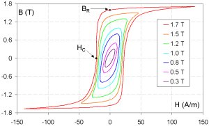
The so called B-H curve gives the relation between the applied fieldstrength H and the resulting induction B. The μ is the angle of the long axis of the ellipses. The relation is μ = B / H. At larger H the ellipses deform because of saturation of the iron. At lower fieldstrengths we see the angle of μ decrease.
(picture source: wikipedia)
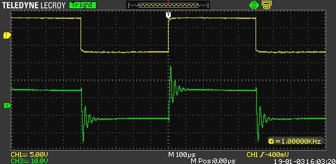
Square Wave Response.
Upper trace: Input signal, lower trace: Output to 1 of the stators. To feed the transformer from a very low impedance a resistive divider was used: from Amplifier output to transformer 4.7 Ohms, parallel to the transformer 0.1 Ohm. For this test an analogue test amplifier was used.
The non-sloping output wave indicates that the transformer does its job up to very low frequencies.
The ringing was further investigated and turned out to be a resonance at 41 kHz with an amplitude of +5.5 dB. Below 22 kHz no more than 1 dB rise in output amplitude was seen. This resonance occurs between the load capacity and the leakage inductance of the transformer.
Calculations for an ESL. Download the spreadsheet.
Most of the calculations speak for them selves.
For the sound pressure at 1 meter distance I introduced an imaginary cylinder of 1 meter radius and 1 meter high, centered around the double cone. This is supposed to be the area over which the radiated energy is distributed. From that the sound pressure at 1 meter distance is calculated.
Of course these are calculations with several assumptions and simplifications which make the results not much more than approximations.
Two conclusions leap to the eye, line 33 tells us that the efficiency of the loudspeaker is very low (but everyone knows that), and line 31 suggests that you do not need much voltage for an electrostatic headphone. I did not work it out but maybe it is feasable with a transformerless vacuum tube solution.