TestTool TPA
The TestTool-TPA can be used to test several functions of the TPA board and the Power board.
The tool contains an Arduino Nano with exactly the same software as on the FLT. The software finds out that is is running on the TestTool by the status of pin D4. On the FLT it is GND, on the Tool it is open.
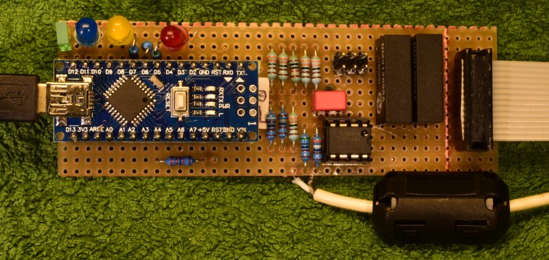
The Flatcable is to connect to the TPA board under test. The USB connector on the Arduino must be connected to a PC on which the program TestTool_TPA runs. The white cable has an RCA connector and should be connected to an audio signal generator. The 6-pole header can be connected to a Power board if that has to be tested too. The TPA board should have its supplies +12 and +50 volts present.
The green led upper left indicates TPA in reset. The other leds are the same as on the FLT board, blue = CPU, yellow = Communication, red = Error.
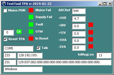
Screenshot of the program TestTool_TPA.
In this picture the TestTool was not connected to a TPA board, but it was supplied with 12 Volt.
Upper left a checkbox to enable the solid-state switch on the Power board, if one is connected. The field Mains Fail will be green if the Neon tube is on, other wise red.
Supply Fail reflects the status of the Supply-Fail bit in the FLT status byte. However this bit is forced to OK when the FLT firmware runs on the test tool.
Fault and OTW show the status of these lines of the TPA3255 chip. OTW will be red if the Clip_OTW line is longer that 2 seconds low, which indicates the Over Temperature Warning.
Clips indicate the number of clipping events modulo 256. Clr will clear the clipcounter.
Reset TPA brings the TPA3255 chip in reset mode, clearing any error condition. On the right the measured voltages +5A, -5A, and +5D are the supply voltages on the TestTool. +50V and +12V are the voltages on the TPA board.
More at the bottom is a field to enter the serial port name and a checkbox to enable communication. If a wrong serial port name is entered an error message appears. After clicking these away another name can be entered. When the tool is properly closed the last used serial port name will be saved and retrieved when the program starts again.
Below that we have counters for incoming and outgoing messages and textboxes displaying the contents of the messages in decimal byte values.
On the bottom line a textbox indicating the Operating System on which the program runs.
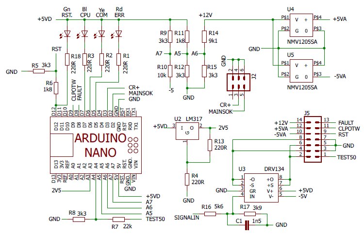
Schema The schema is mainly a subset of the FLT-4 bord.
The TestTool is supplied by the +12V from the TPA board, the Arduino is suplied by the USB cable.
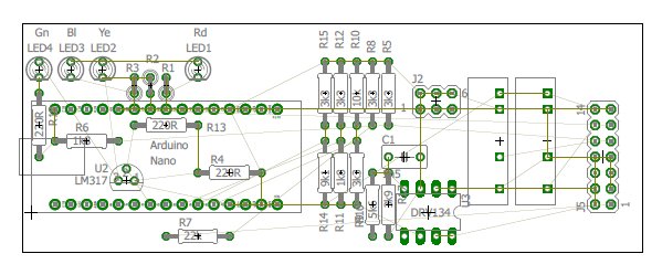 Board
BoardThe board has not been routed as a real PCB, this layout was made to help hand-wiring it.